1.1 current situation of water wall tubes in power plants
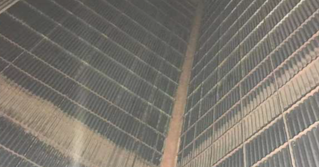
water walls are the primary heating surfaces of power plants. composed of multiple rows of riser tubes, they fit closely against the furnace walls and form the inner lining around the furnace chamber. the inner side of water walls is the fire-facing side, and the outer side is the fire-back side. the fire-facing side is in direct contact with the furnace flame.
1.2 common defects of water wall tubes
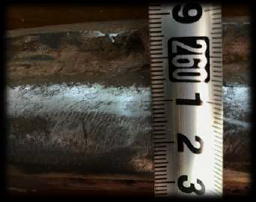
water wall tube rupture frequently occurs during the operation of thermal power plants. samples were taken from the ruptured water wall tubes of a power plant, and analysis on the rupture locations revealed that the cracks were induced by thermal fatigue stress.
under high-temperature operating conditions, oxide scale tends to form on the inner surface of water wall tubes, while both oxide scale and scaling accumulate on the outer surface. this significantly impairs the heat transfer between the inner and outer tube walls.
during plant operation, periodic fluctuations of the furnace flame will lead to cyclically varying temperature differences across the tube walls, which in turn generates considerable thermal fatigue stress. the cyclic action of such stress causes continuous accumulation of plastic deformation damage and eventually initiates thermal fatigue cracks. as thermal stress persists, the cracks keep propagating until the tubes rupture completely.
1.3 limitations of conventional testing for water wall tubes
surface non-destructive testing (ndt) for in-service water wall tubes mainly applies penetrant testing (pt) and magnetic particle testing (mt). nevertheless, these two methods have stringent requirements on the tube surface, which demands a large quantity of grinding work. meanwhile, they are characterized by low testing efficiency and long inspection cycles.
furthermore, the grinding process may cause abrasion to the tubes, resulting in wall thickness reduction and deterioration of safety performance. this will bring potential safety hazards and considerable economic losses to the operation of power plants. in addition, conventional single-channel eddy current testing only covers a small area in a single scanning pass, leading to low working efficiency.
in view of the above limitations, experimental results verify that multi-channel and multi-coil eddy current testing and array eddy current testing (eca) can inspect water wall tubes rapidly and effectively. the following sections mainly compare the defect detection performance of multi-channel & multi-coil eddy current testing and array eddy current testing for water wall tubes.
2.1 overview of array eddy current testing
array eddy current technology uses multiple eddy current testing coils, which are specially designed and packaged in accordance with the geometric profile of inspected workpieces. supported by electronic control and signal processing, it enables rapid and effective defect detection for materials and components.
during operation, the dedicated electronic control system coordinates each group of coils to perform electromagnetic excitation and signal acquisition. the feedback electromagnetic induction signals are further processed by professional algorithms for computational analysis, noise reduction, signal discrimination and data interpretation. this method can accurately detect various latent damages and defects on the surface and near-surface of metallic materials and mechanical parts, such as cracks, corrosion pits, material inclusions and wall thickness reduction.
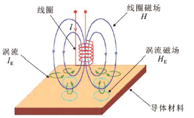
2.2 principles of array eddy current testing
array eddy current testing (eca) adopts specially structured eddy current coils. supported by the analysis, calculation and data processing functions of computers, it achieves rapid and efficient inspection of materials and components.
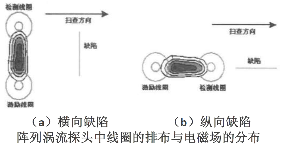
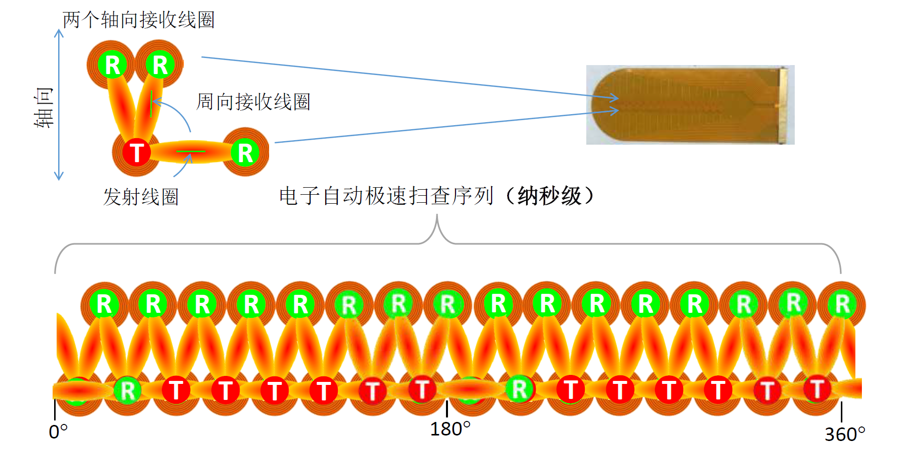
compared with conventional eddy current testing, the major distinction of eca lies in its probe, which is assembled from multiple independently operated coils arranged in a specific layout. electromagnetic fields propagate in two mutually perpendicular directions between excitation (also referred to as transmitting) coils and detection (also referred to as receiving) coils, as illustrated in the figure on the right.
this unique coil arrangement facilitates the identification of linear defects with diverse orientations and addresses the inherent shortcoming of ordinary eddy current coils — high directional sensitivity to defects.
2.3 coil configurations of array eddy current testing
2.4 testing equipment of array eddy current testing
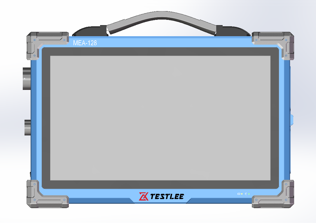
the mea-128 portable array eddy current detector is equipped with 128 channels and supports multi-channel synchronous signal acquisition as well as 3d imaging, featuring high detection sensitivity and efficiency.
it can accurately identify various defects on the surface and near-surface of all types of conductive materials. the instrument is applicable to working conditions such as welds and pipes, and fully complies with industrial testing standards. with a portable design, it is widely used for various industrial non-destructive testing operations.
3.1 experimental study on array eddy current testing
preparation of reference test tubes
the reference test tubes are made of 15crmo steel, with a length of 400 mm and dimensions of φ32×6.2 mm (outer diameter 32 mm, wall thickness 6.2 mm). the tube surfaces shall be thoroughly clean and free of grease, rust and other contaminants, and the surface roughness shall not exceed 25 μm.
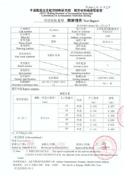
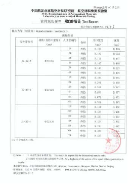
the fabrication and certification of the test tubes are entrusted to the aeronautical materials testing laboratory, aecc beijing institute of aeronautical materials. electrical discharge machining (edm) is applied for sample processing. all notch defects on the tubes are perpendicular to the tube wall surface. the allowable depth tolerance of the notches is ±15% of the notch depth or ±0.05 mm.
3.2 experimental study on array eddy current testing (different crack lengths)
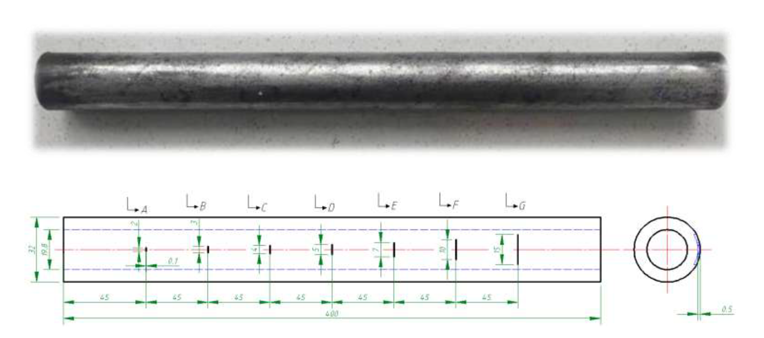
reference test tube 1
for the simulated cracks on this tube, the depth and width are kept constant while the length is varied. all cracks are perpendicular to the tube axial direction (90°). the crack depth is 0.5 mm and the width is 0.1 mm. the crack length l is set to 2 mm, 3 mm, 4 mm, 5 mm, 7 mm, 10 mm and 15 mm respectively.
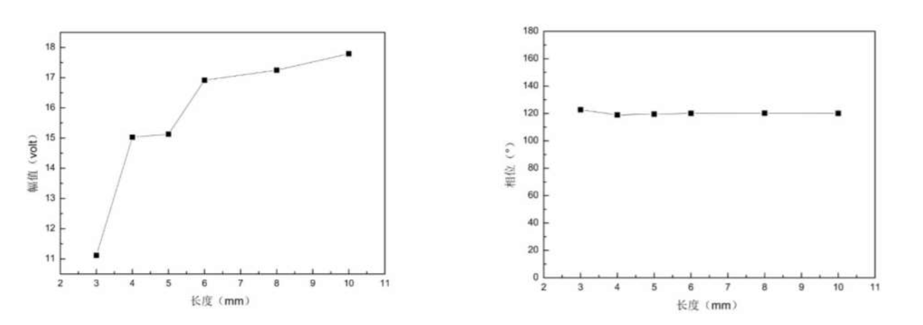
effect of different crack lengths on eddy current signals
the research on characteristic parameters of crack length indicates that when the width and depth of cracks are fixed, the crack length has an approximately linear correlation with signal amplitude. the amplitude rises gradually as the crack length increases. meanwhile, the phase value remains within the range of 118.9 to 122.7 and varies slightly
3.3 experimental investigation on array eddy current testing (cracks of varying depths)
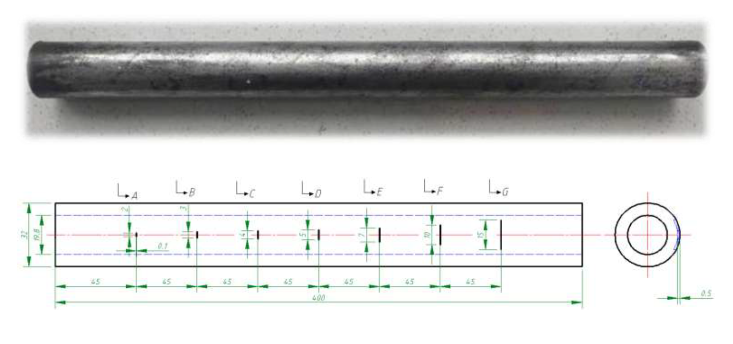
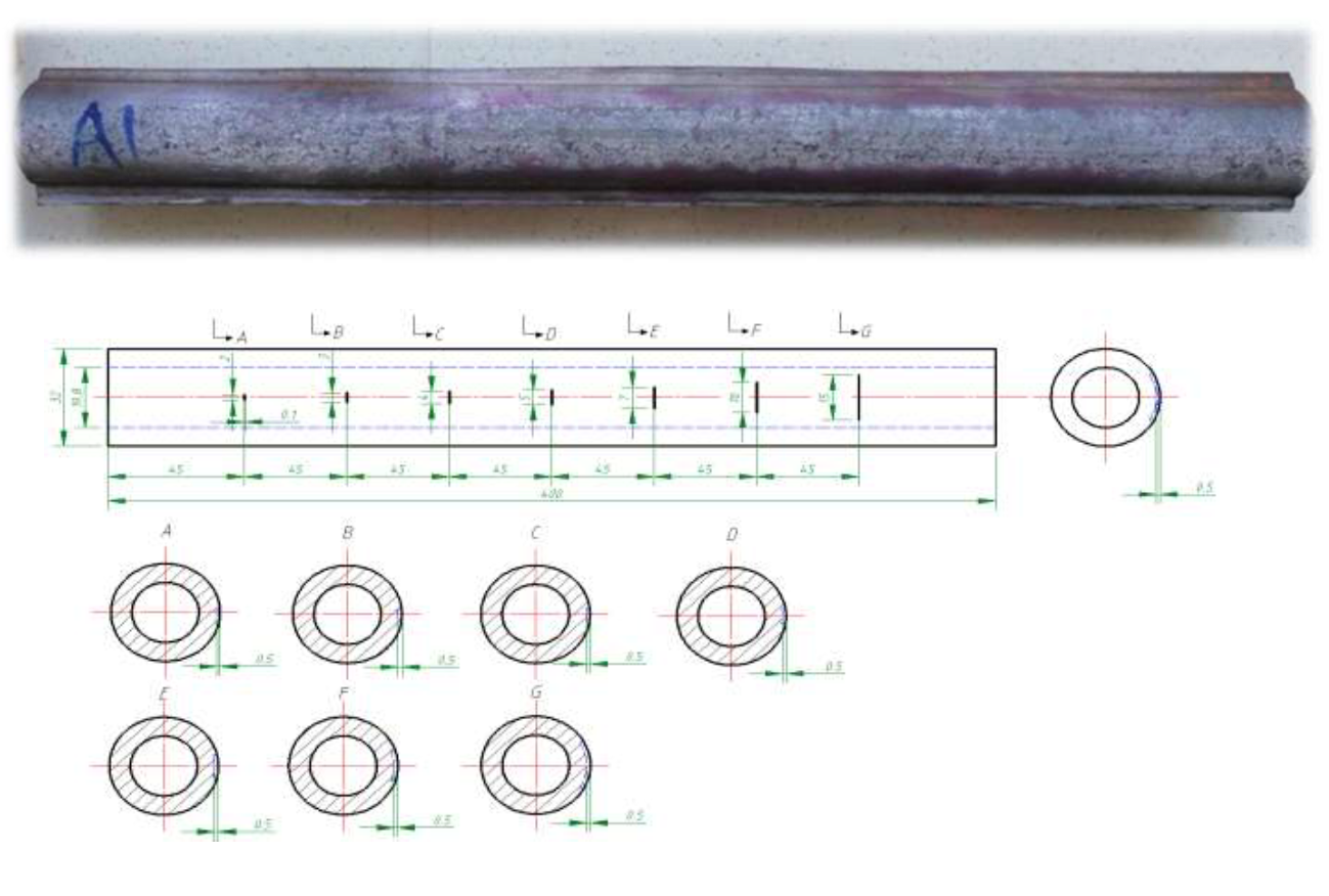
reference test tube 2
for the simulated cracks, the length and width are kept constant while the depth is adjusted. all cracks are perpendicular to the tube axial direction (90°). the fixed crack length is 5 mm and the width is 0.1 mm. the crack depth d is set to 0.3 mm, 0.4 mm, 0.5 mm, 0.7 mm, 0.8 mm, 1.0 mm and 1.2 mm respectively.
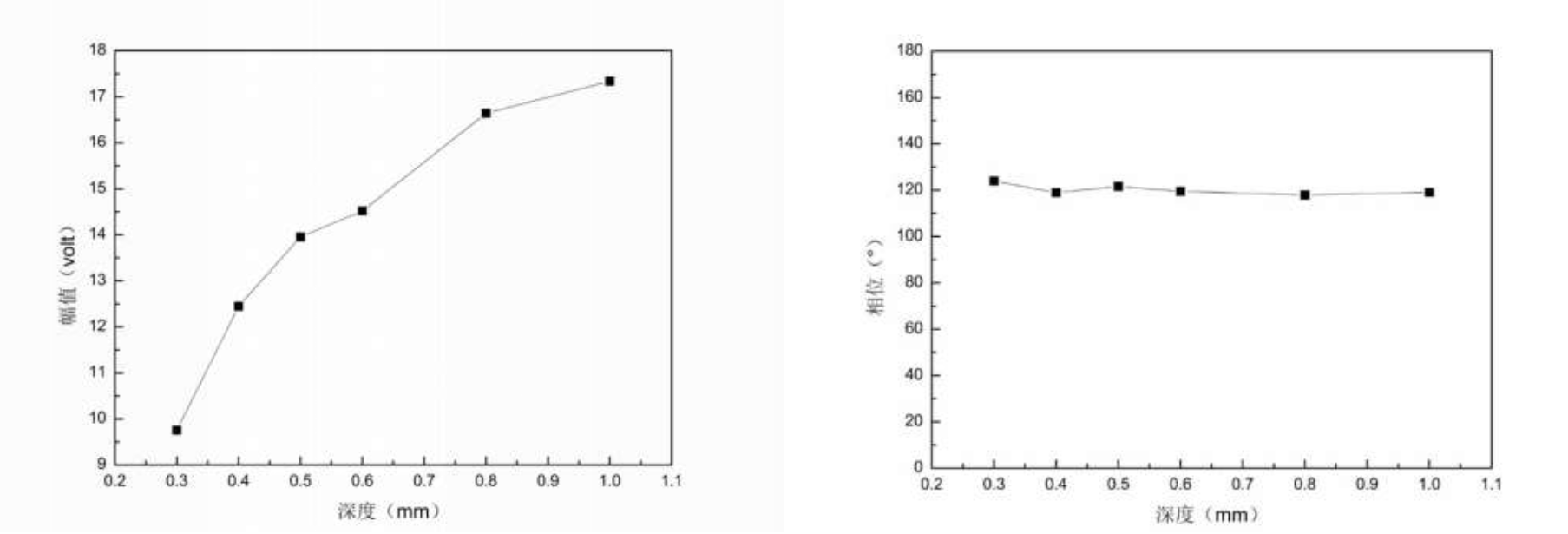
effect of different crack depths on eddy current signals
research on the characteristic parameters of crack depth shows that when the width and length of cracks are kept constant, crack depth presents an approximately linear correlation with signal amplitude. the amplitude increases gradually as the crack depth grows. the phase value stays within the range of 117.9 to 124 and varies slightly.
3.4 experimental study on array eddy current testing (different crack angles)
reference test tube 3
for the simulated cracks, the length, depth and width are kept constant while the crack angle is varied. the fixed crack dimensions are 5 mm in length, 0.5 mm in depth and 0.1 mm in width. the angles between the cracks and the tube axial direction are set to 90°, 75°, 60°, 45°, 30°, 15° and 0° respectively.
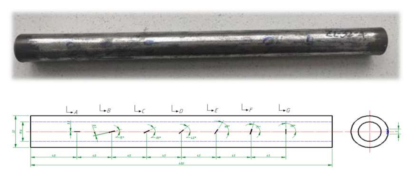
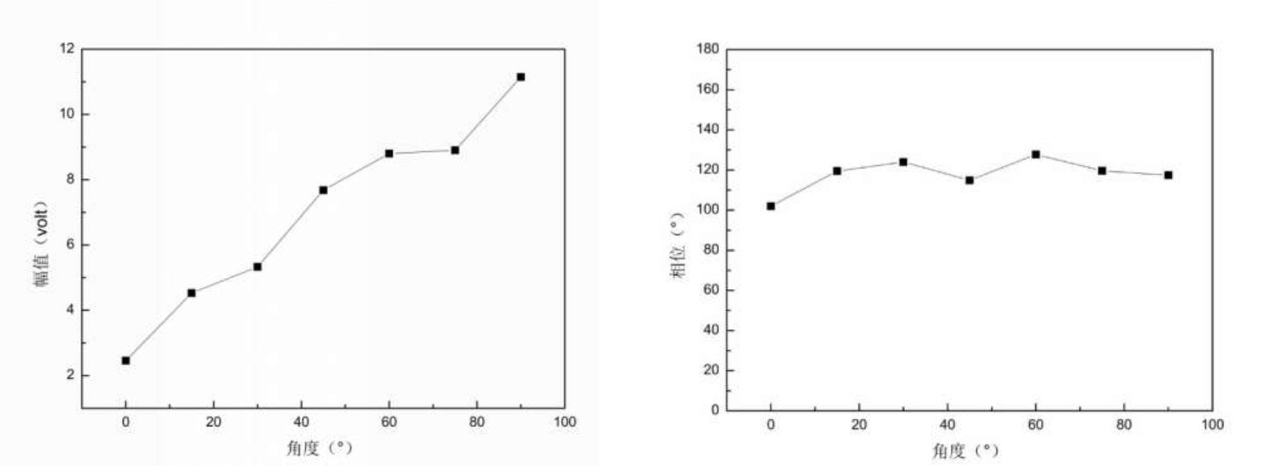
effect of different crack angles on eddy current signals
the research on characteristic parameters of crack angle shows that when all other crack characteristic parameters are kept constant, the signal amplitude increases continuously as the crack angle becomes larger. no definite correlation exists between the phase value and crack angle.
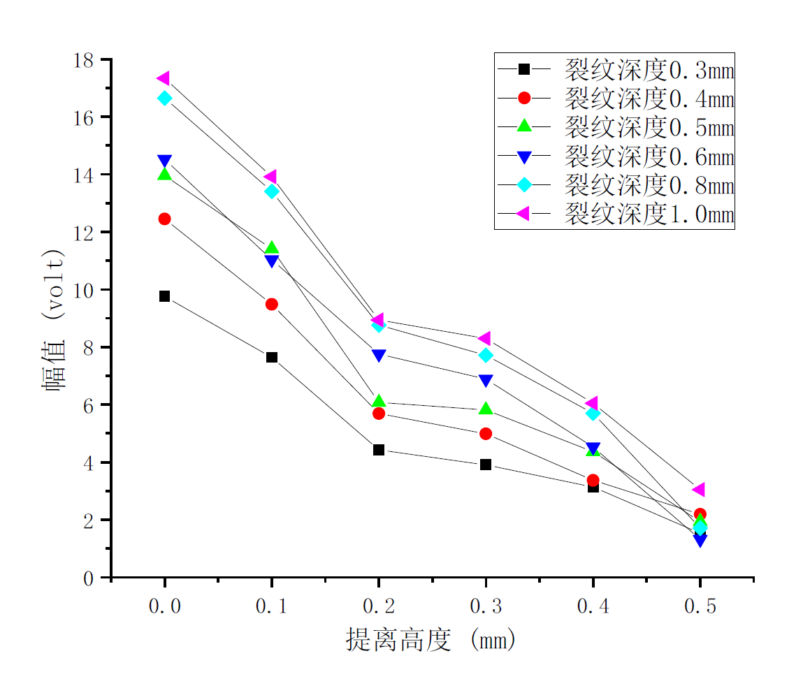
3.5 experimental study on array eddy current testing (different lift-off heights)
research on the characteristic parameters of lift-off shows that when all other characteristic parameters of cracks remain unchanged, the signal amplitude decreases gradually as the lift-off height increases.
lift-off tests were carried out on the flexible probe. when the thickness of the attached shim reached 0.4 mm, the amplitude of the eddy current signal dropped below 30%, which significantly impaired the detection reliability. for this reason, the adverse effects caused by excessive lift-off height shall be avoided during inspection.
3.6 experimental study on array eddy current testing (effect of scale)
the research on characteristic parameters of crack length for scale-covered test tubes reveals that when the width and depth of cracks are kept constant, crack length presents an approximately linear correlation with signal amplitude. the amplitude rises gradually as the crack length increases. nevertheless, the detected amplitude is distinctly lower than the measurement results from smooth test tubes.
4. experimental conclusions
through investigating the effects of crack length, width, depth, angle, lift-off height and surface scale on eddy current signals, the following conclusions are drawn:
when the width and depth of cracks are kept constant, crack length has an approximately linear correlation with signal amplitude. the amplitude increases gradually as the crack length rises, while the phase varies slightly.
when the width and length of cracks are kept constant, crack depth presents an approximately linear correlation with signal amplitude. the amplitude increases gradually with the growth of crack depth, while the phase remains nearly unchanged.
the research on the influence of different crack angles on eddy current defect signals shows that the signal amplitude increases continuously as the crack angle becomes larger. no definite correlation exists between the phase and crack angle.
studies on lift-off characteristic parameters indicate that with all other crack parameters unchanged, the signal amplitude declines gradually as the lift-off height increases. when the thickness of the attached shim reaches 0.4 mm, the amplitude of eddy current signals drops remarkably, which adversely affects detection reliability. accordingly, the negative impacts resulting from excessive lift-off height shall be avoided in practical testing.
the investigation on crack length parameters of scale-covered test tubes for eddy current defect signals reveals that the test rules are consistent with those of smooth test tubes. despite a slight reduction in measured amplitude, all defects can still be clearly detected. it proves that the array eddy current testing technology achieves excellent detection accuracy when applied to unpolished water wall tubes.